
|
|
TripMate Self Start ModificationThis page contains two separate modifications to the TripMate GPS unit. This tripMate is a very convenient little GPS to use with a mobile tracker. It is designed to be used with a laptop computer and the only way to turn it on is with a special command from the computer. The first mod will cause the tripMate to come on as soon as power is applied. No more tricky adapter cables to trick it into starting! The GPS can still be used with Delorme's Street Atlas software by selecting "generic NMEA" instead of TRIPMATE. The second modification will provide a 5 volt regulated power supply so that you can feed this GPS with 12volts on pin 9 of it's serial connector. Most TNCs can provide 12volts by simply installing a jumper. Self Start Modification The TripMate has 3 modes of operation.
First it must be placed in STANDBY mode. Then it must hear the word "ASTRAL" on it's receive serial port. This modification will cause the unit to enter STANDBY mode anytime power is applied, and will cause the TripMate to hear the word "ASTRAL" so it will turn on it's receiver 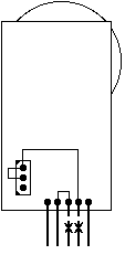
This is the TripMate GPS we'll be working with 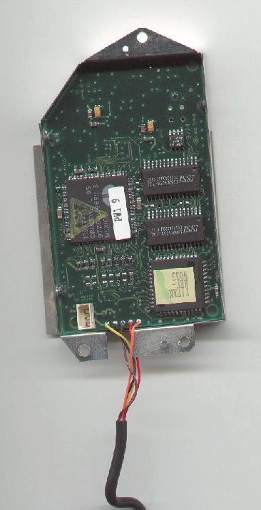
Remove the battery housing, and the metal plate covering the circuit board. Notice the battery plug in the lower left and the 5 wires just to the right along the bottom edge. These wires are from the 9 pin serial connector. Here are the wires we'll be working on. From left to right they are: Yellow)Pin 9 - Connects directly to the center of the nylon battery plug - can be used to power TripMate Black)Pin 2 - Data out from the GPS Brown)Pin 3 - Data in to the GPS Red)Pin 4 - DTR used to power GPS on Orange)Pin 5 - Ground Now we will begin the actual modification to your TripMate Please note this is not for the faint of heart, folks with shakes or bad eyes. 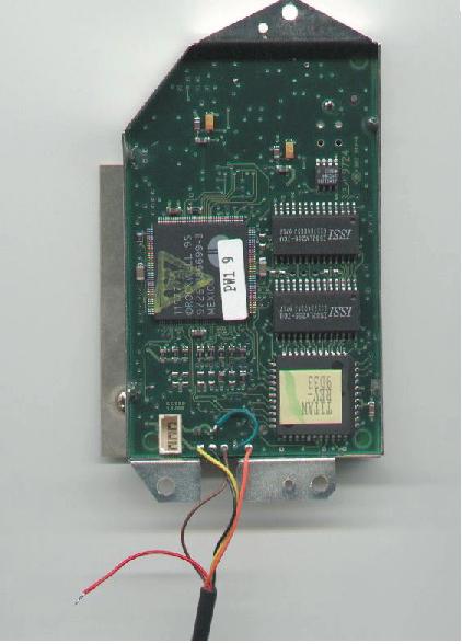
Unsolder the wire on solder pad 4 (RED) from the tripMate circuit board and insulate the exposed end. Install a 1 inch jumper wire(in this example, the GREEN jumper) between the battery "+" connector and where the RED wire was soldered to the PCB. This causes the unit to enter STANDY mode whenever power is applied. If power were applied right now, the TripMate would send the word "ASTRAL" on it's serial port every second. 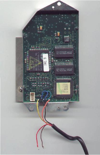
Unsolder the wire on solder pad 3 (BROWN) from the tripMate circuit board and insulate the exposed end. Install a 1 inch jumper wire (BLUE JUMPER) between Solder Pad 2 and Solder Pad 3 (Note that the original BLACK wire is still attached to Solder Pad 2. This connects data in/out together so that the GPS will self start. In order for the TripMate to turn ON, it must receive the word "ASTRAL" on it's serial port. Fortunately, TripMate sends the word "ASTRAL" about once a second when it is in STANDBY mode. By shorting pins 2 and 3 together with the BLUE jumper, we allow it to hear the word "ASTRAL", and the unit is tricked into turning ON. Check very carefully for stay strands of wire from your soldering. Perform a continuity test to insure that the center pin of the battery connector is NOT connected to anything other than solder pad 1 (YELLOW ). Reassemble the unit. You are now the proud owner of a TripMate that will self start as soon as the batteries are hooked up! Please test the GPS by installing the batteries before proceeding to the next step. 12 Volt Power Modification In addition to the above mod, you can rob the tiny pins from a sound blaster CD Audio cable and plug them into the nylon plug body that is hooked to the battery holder on the TripMate If you are careful with a jeweler's screwdriver you can pry the little locking tabs up on the nylon plug body and extract the wires that are connected to the battery pack. Replace these wires with the wires you removed from a sound blaster audio cable. See the pictures below for more details. 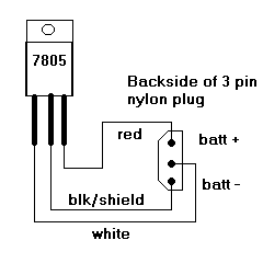 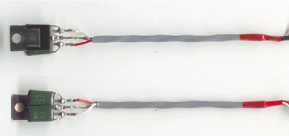
Believe it or not, there is a 7805 regulator underneath those epoxy capacitors. Their value is not critical I used .022uF. Notice that each cap is soldered from an outboard pin on the 7805 to the center ground pin. The white wire connected to the left pin on the 7805 is 12v+ input, the red on the right pin is 5v+ regulated output. The center lead of the 7805 is connected to the shield of the sound blaster cable. Notice the locking tabs and the sequence of the wires. The hole in the heat sink of the regulator can be screwed to one of the screws that hold the bottom cover of the tripMate on. Not only does this keep the 7805 out of trouble, but also acts as a heat sink. Since most TNC's are able to supply 12v+ on an unused serial pin, this is a very convenient way to supply power to the GPS. Paccomm TNC's use this pin for CO-AX lan, and it can be easily modified to provide 12v+. Kantronics products have jumpers that can supply power on either pin 13 or pin 25 of the serial port (or pin 7 of the KPC3plus radio port). You will have to build a cable to connect pin 25 to pin 9! A standard db9 to db25 adapter that you buy in a store will not work! Here is the diagram: 9pin--->25pin 2------>2 5------>7 9------>25or13 |
Page last updated:
October 3, 2013 15:15
|
