The N3UJJ
Multi Band Cage Dipole
Antenna Project
The goal of the "Antenna Project" is to come up with an efficient Multi Band Horizontal Dipole antenna that could fit on my small property.
By efficient we mean an antenna that will radiate 90% or more of the energy output from the transmitter/amplifier, without a tuner and without using ladder/window line.
The problem with multiband HF antennas and coax is LOSS, the only way we can the full bandwidth on each band with a low SWR is with a cage dipole, so the plan was to see if we can get a Multi-Band cage dipole built in a fan or parallel configuration.
Prototype Number One
What you see above is prototype #1 of the N3UJJ Parallel-Cage Dipole
note.. above picture (and link are 5 pictures merged together)
for a Hi-Rez (35 meg) image click here
Prototype # 1 was a "Dual Band" (40 -20 Meter) Parallel Dipole Antenna, each Dipole is a "Cage Dipole"
SWR was BELOW 2.3 (1.1 at lowest point), for ALMOST the FULL BAND on 40 Meters, and under 1.5 for the FULL BAND on 20 meters.
All readings were taken with a Array Solutions AIM-1470b Antenna Analyzer
This meant basically that we were radiating 95% of the energy that it was feed with.
This antenna was built with standard 12 gage electrical wire.
3 inch PVC spreaders on the 40 meter band, and 1.5 inch PVC spreaders on the 20 meter band.
The antennas were separated vertically in the center by a 24" Plexiglas Lexan spreader, feed at the bottom with a DX Engineering DXE-BAL050-H05-A Balun.
I used the JEFA Tech Low Loss 400 cable from the shack to balun.
A week-Long automated propagation test (using PSK Reporter) showed outstanding results
Not only did this antenna work great for getting out, reception was OUTSTANDING !!!!!
The old saying "You can't work what you can't hear" also proved to be correct.
THIS ANTENNA COULD REALLY HEAR !!!!
Prototype #1 was constructed of the following:
8 one inch PVC couplers (20 meter spacers)
16 three inch PVC couplers (40 meter spacers)
650 feet of 12 gauge stranded (insulated) wire
26 inch (by 3) 1/4 inch Lexan (to space Dipoles)
2 48 inch aluminum channels (end spacers)
Rubber "Bungies" (as tension devices)
4 copper grounding lugs
Misc. Screws and nuts
Prototype #2 was a "4 Band" ( 40 - 30 - 20 - 10 meters) antenna.
The first (and most important) goal was to get the FULL 40 meter band at less than 1.5 SWR, calculations showed this would require a cage of almost 6 inches.
One big consideration was weight, 4 cage dipoles for 40/30/20/10 uses almost 1,000 feet of wire.
That alone is going to make for a heavy antenna, what's going to happen in a ice storm or sleet?
Prototype Number Two
What you see above is prototype #2 of the N3UJJ Parallel-Cage Dipole
(click the above picture for a full size image)
This picture was taken just after assembly, and it was near the end of the day and it was getting cold
So we called it a day.
Prototype 2 was a huge success!
After tuning we had less than 1.5 to 1 SWR on all bands, for the full band (on each band)
BUT...
It was heavy (almost 70 pounds), and it did not survive the winter, the second ice storm we had, ripped the limbs right out of the trees.
The antenna survived the fall to the ground with no damage. For this to work we were going to have to cut the weight in half.
Prototype 2 used the following
850 feet of 12 gauge stranded (insulated) wire
6 inch PVC spacers on the 40 meter band
4 inch PVC spacers on the 30 meter band
2 inch PVC spacers on the 20 meter band
1.5 inch PVC spacers on the 10 meter band
36 inch (by 3) 1/4 inch Lexan (to space Dipoles)
and the same DX Engineering DXE-BAL050-H05-A Balun, and JEFA Tech Low Loss 400 cable from the shack to balun.
You can see in the picture the antenna has not been tuned, in fact the new end spreader bars have not been installed and tension devices haven't been adjusted.
In the above configuration, (just pulled in the air) the SWR on all 4 bands is well below 2.5
Prototype Number Three
What did we learn from cage dipole prototype number 2?
1. The design works !
2. It's way to heavy
So, the plan for Prototype 3 was to use U/V Resistant foam for the spacers
And drop the wire down to 14 gage electrical wire.
This did in fact drop the weight in half.
Again the antenna worked GREAT!
BUT...
Over time the 14 gauge wire kept breaking at the center support (on the 40 meter cage). The 40 meter cage took the full weight of the antenna and all the flexing as the antenna blew in the wind. The problem was that all the cages needed tension on them to keep the "cage" shape.
But this antenna worked GREAT!
Prototype Number Four
Summer of 2011
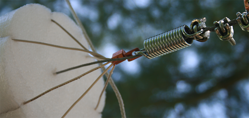
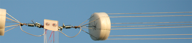
I think I have worked out how keep the support weight (and stress) off the top cage.
I have surrounded an 1/8" steel cable with the top cage, and use lightweight springs to keep tension, the steel cable passes through the center of the spring (on each end) and serves to keep slight tension on the the 40 meter cage (to keep the wires from sagging)
See pictures below:
I'll keep everyone posted how it works
Links that were used to help design this antenna
Parallel Dipole construction
Resonant Frequency, Bandwidth and End-Effect of a Wire-Cage Dipole Antenna
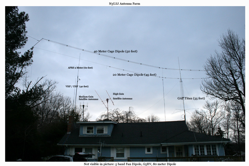
Below is a very old picture of my house with prototype 1 in the air
Click here to see my HamShack and RigControl
Click here to see the Antenna Analysis (AIM4170b) of my Antennas |